Over the years I have been working with a lot of different software suites and tools to get my 3d modeling and cad design done.
Some of the the solutions were better than others. Most of the are pretty similar.
One of the tools has always been somewhat different. Still as a programmer, who loves coding and is used to working within a text editor, there is a lovable tool out there.
It is called OpenSCAD.
Benefits of using OpenSCAD:
- versioning using git
- works in your vim
OpenSCAD
Installation
While writing this article I am working on a windows machine.
So here is what I did to get started on windows:
- Open Powershell (Win + R, type "powershell", hit enter)
- Paste the command from the downloads page
winget install --id=OpenSCAD.OpenSCAD -e
- Confirm windows warning about system changes
After that you can find a link to the OpenSCAD gui in your windows start menu.
- Follow the instuctions at the OpenSCAD User Manual on how to use an real text editor (vim)
Thats all. Now you can start playing around with OpenSCAD.
Also not that there is vim-lsp plugin for openscad. I installed it using the command LspInstall openscad_lsp within my LazyVim setup
Usage
I will not repeat what other, better people have been explaining much more precise than I ever could. Instead here are a few references that I liked:
So here is what I came up with after 3 or 4 hours of work. I guess in freecad it would have take me almost the same time.
/*
* TODOs:
* - warnings for max bridge length, impossible overhangs and so on
*/
// all units are in milimeters
moduleSize = 4; // thickness of a single module
railWidth = 8;
railHeight = 4;
wallWidth = 2;
holeDepth = 0.6;
snapHoleDepth = 0.3;
snapHoleHeight = 1.4;
snapArmLength = railHeight - 0.5;
snapArmThickness = 0.6;
snapBaseThickness = 0.6;
clearance = 0.25;
tightClearance = 0.1;
tiny = 0.005;
pinWidthRespectingClearance = moduleSize - wallWidth - (2 * clearance);
overallSnapWidth = railWidth + 2 * snapArmThickness + 2 * clearance;
module railModule() {
module baseModule() cube([moduleSize, railWidth, railHeight]);
module topHole() translate([wallWidth / 2, wallWidth, railHeight - holeDepth]) cube([moduleSize - wallWidth, railWidth - 2 * wallWidth, holeDepth + tiny]);
module snapHole(offsetY = 0) translate([wallWidth / 2, offsetY, railHeight - snapArmLength]) cube([moduleSize - wallWidth, snapHoleDepth + tiny, snapHoleHeight]);
difference() {
baseModule();
topHole();
snapHole(-tiny);
snapHole(railWidth - snapHoleDepth);
}
}
module snapModule() {
module snapBase()
translate([0, -clearance - tiny / 2, tightClearance])
cube([moduleSize, railWidth + 2 * clearance + tiny, snapBaseThickness]);
module snapPin()
translate([wallWidth / 2 + clearance, wallWidth + clearance, -holeDepth + tightClearance - tiny])
cube([pinWidthRespectingClearance, railWidth - wallWidth * 2 - 2 * clearance, holeDepth + tiny]);
module snapArm(offsetY, _mirror = 0) {
translate([0, -snapArmThickness - clearance + offsetY, -railHeight]) mirror([0, _mirror, 0]) {
cube([moduleSize, snapArmThickness, railHeight + snapBaseThickness + tightClearance]);
translate([wallWidth / 2 + clearance, snapArmThickness, railHeight - snapArmLength + clearance]) cube([pinWidthRespectingClearance, snapHoleDepth, snapHoleHeight - 2 * clearance]);
}
}
translate([0, 0, railHeight])
union() {
snapBase();
snapPin();
snapArm(0);
snapArm(overallSnapWidth, 1);
}
;
}
module snap(moduleCount = 1) {
for (i = [0:1:moduleCount - 1])
translate([i * moduleSize, 0, 0])
snapModule();
}
module rail(moduleCount = 1) {
for (i = [0:1:moduleCount - 1])
translate([i * moduleSize, 0, 0])
railModule();
}
module sector(radius, angles, fn = 24) {
r = radius / cos(180 / fn);
step = -360 / fn;
points = concat(
[[0, 0]],
[
for (a = [angles[0]:step:angles[1] - 360]) [r * cos(a), r * sin(a)],
],
[[r * cos(angles[1]), r * sin(angles[1])]]
);
difference() {
circle(radius, $fn=fn);
polygon(points);
}
}
module arc(radius, angles, width = 1, fn = 24) {
difference() {
sector(radius + width, angles, fn);
sector(radius, angles, fn);
}
}
module coin() {
//€2. Diameter: 25.75mm. Thickness: 2.20mm. Weight: 8.50g.
linear_extrude(2.2) circle(d=25.75, $fn=40);
}
module cuttingBoardHolder(railLength = 100, outerWidth = 80, snapModuleCount = 2, boardSizes = [1]) {
standThickness = snapModuleCount * moduleSize;
innerRadius = (outerWidth / 2) - overallSnapWidth;
cutoutAngle = 5;
cutoutWallThickness = overallSnapWidth / 3;
railOffset = outerWidth / 2 - railWidth - clearance - snapArmThickness;
module stand() {
union() {
translate([0, railOffset, 0]) snap(snapModuleCount);
translate([0, -railOffset - railWidth, 0]) snap(snapModuleCount);
translate([0, 0, railHeight + tightClearance + snapBaseThickness - tiny]) rotate([0, 90, 0]) {
difference() {
linear_extrude(standThickness) arc(innerRadius, [270, 90], overallSnapWidth, 800);
translate([0, 0, -tiny]) linear_extrude(standThickness + 2 * tiny)
offset(r=1, $fn=50) offset(delta=-1) arc(innerRadius + cutoutWallThickness, [270 - cutoutAngle, 90 + cutoutAngle], overallSnapWidth - 2 * cutoutWallThickness, 800);
}
}
}
}
translate([0, railOffset, 0]) rail(railLength / moduleSize);
translate([0, -railOffset - railWidth, 0]) rail(railLength / moduleSize);
stand();
snapSize = moduleSize * snapModuleCount;
slots = [for(o = 0,i = 0;i < len(boardSizes);o = o + (ceil((boardSizes[i] / moduleSize)) * moduleSize) + snapSize,i = i + 1)o + (ceil((boardSizes[i] / moduleSize)) * moduleSize) + snapSize];
for (slot = slots) translate([slot, 0, 0]) stand();
}
translate([0, -75, 0]) coin();
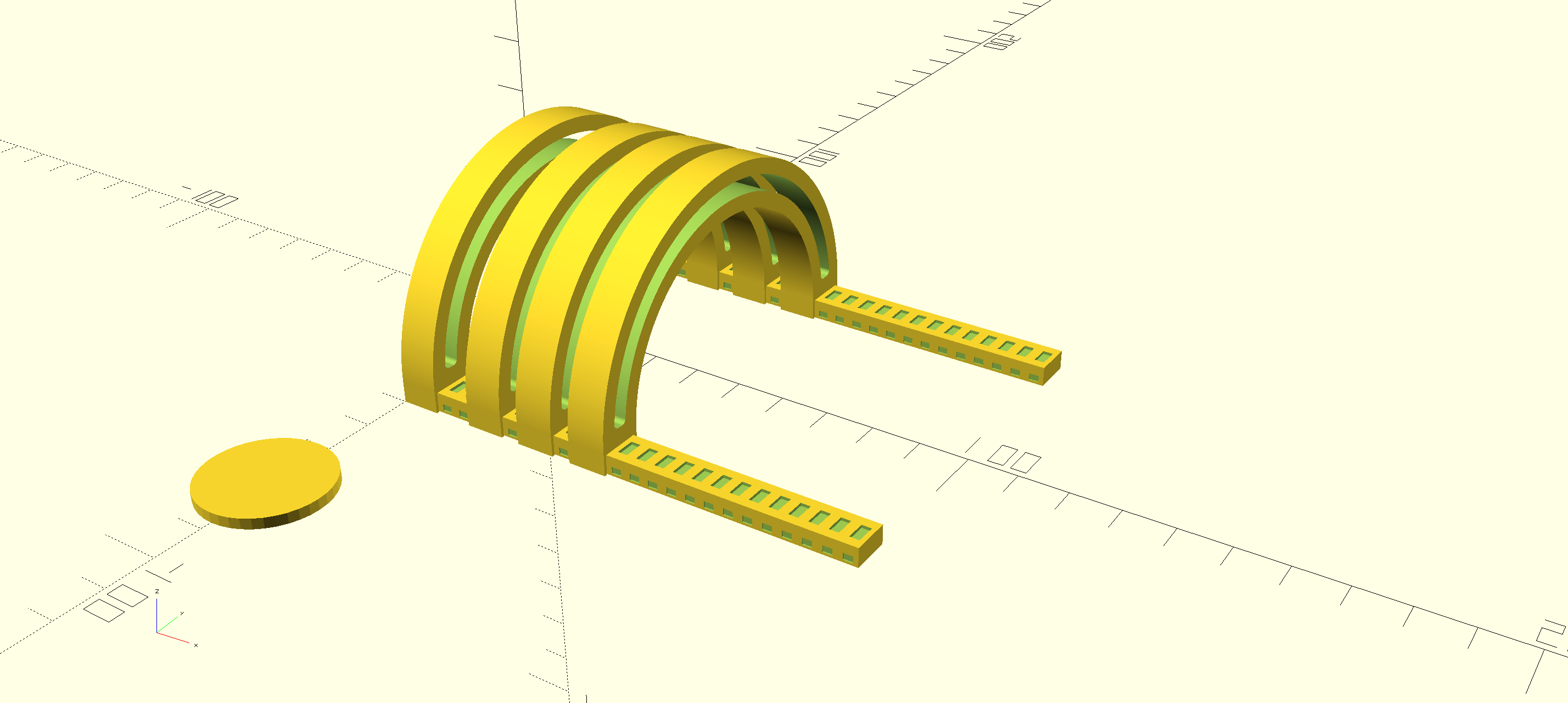
cuttingBoardHolder(railLength=100, outerWidth=80, snapModuleCount=2, boardSizes=[5, 4, 1]);
Which when rendered looks like this.
Printing the model
Export as STL
To export the .stl file for loading into your favorite slicer software the follow those two steps:
- Design -> Render (F6)
- File -> Export -> STL Export (F7)
The render step takes quite a while (for me it is around 2 minutes). After that save the resulting stl file to a place where you can find it.
Open up PrusaSlicer and load the stl file. Right click the model in the model tree and click "Split -> Into Objects"
When doing this for the first time my model was split into much more parts than I was expecting.
I fixed the problem by adding tiny offsets my design in some places so that there is always an overlap > 0 between connected parts.
Sometimes this tiny offset is also called eps.
I adjusted the parts orientation such that they are laying flat for optimal printing.
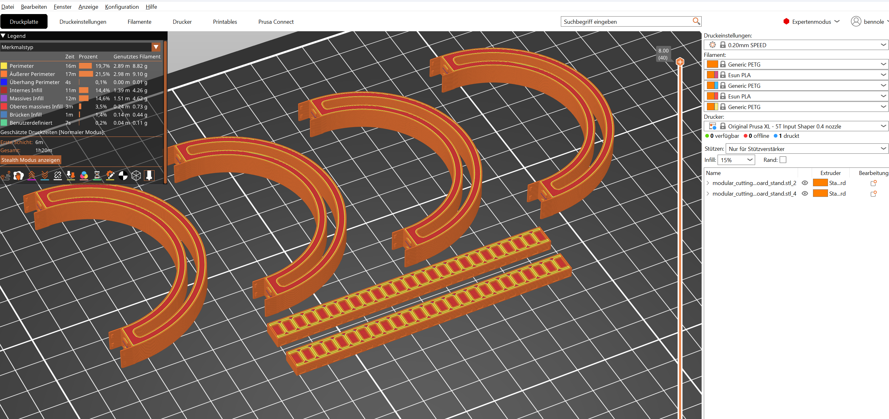
I left all the settings at their default values (no support, .2mm speed profile) and went on to print my model usin white eSUN ePETG filament on my prusa xl.
The print time was estimated to be ~1h 20min.
Here is a screenshot of the sliced model in prusa slicer including the statistics in german.
One and a half hour later I presented the finished print to my family!
TODO: Add photo of the finished print
What I have learned
Always add a reference object to your scene before printing. It helps a lot in visualizing dimensions and picking sensible values.
In my example I have used a 2€ coin as a reference.
For loops in OpenSCAD are a litte bit funny. Accumulating a feels pretty strange to me. Also I should have read the documentation on variables.
Ideas
- OpenSCAD library for reference objects: coins, lighters, matches, ...
- Investigate how all the global variables can be avoided and make a library module out of my rails